

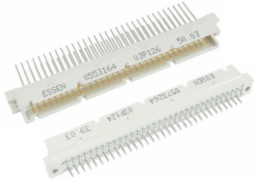
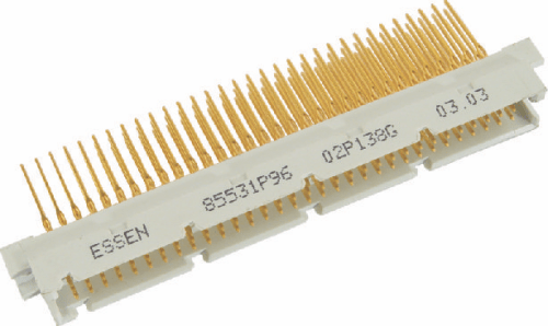
857-SERIES
- Characteristics
- Products
Characteristics
- Inverted version of standard euro connector (854 Series).
- Similar to series '855' except that it has an offset of 0.73 mm. between the centre of the mounting hole and the center of the termination points row B of the male connector.
- In this system, male fitted with male contacts is mounted on the back panel and female fitted with female contacts is mounted on the daughter board.
- Find application in the field of telecommunications, Electronic Instruments,control and computers.
Technical Data
Size
Contact Spacing
Polarisation
Operating Current
Operating Voltage
Withstand Voltage
Insulation Resistance
Contact Resistance
Operating Temperature
Insulation Material
Contact Material
Contact Finish
Insertion Force
Withdrawal Force
Contact Retention
Mechanical endurance
Form HE-11 - 32, 48,64,96
2.54 / 5.08 mm.
Connector shape
3A max.at 8S°C
350V DC or AC peak
1000V rms between contacts and 1550V rm between contact and ground for one minute.
5000 Mohm min.
15 mohms max.
-55°C to +125°C
Flame retardant thermoplastic UL94V-O
Copper alloy
Contact zone - selectively gold plated termination zone - tin lead or gold
96Way≤90 N
64Way≤60 N
48Way≤45 N
32Way≤30 N
96Way≥15 N
64Way≥10 N
48Way≥9 N
32Way≥5 N
Male 20 N Min.
Class I 500 cycles
Class II 400 cycles
Class Ill 50 cycles
MALE, STRAIGHT DIP SOLDER/ WIRE WRAP (Three Row)

No. of Contacts
- 96
- 64
- 64
- 48
- 48
- 32
- 32
- 32
- 32
Contact arrangement
- 96a,b,c
- 64a,c
- 64 b,c
- 48 a,b, c (odd)
- 48 a,b, c (even)
- 32 a,c (odd)
- 32 a,c (even)
- 32a
- 32 C
Ordering code
- 8573296 ( ) P13*
- 8573264 ( ) P12*
- 8573264 ( ) P14*
- 8573248 ( ) P17*
- 8573248 ( ) P18*
- 8573232 ( ) P15*
- 8573232 ( ) P16*
- 8S73232 ( ) P10*
- 8573232 ( ) P11*
MALE, PRESS FIT, STRAIGHT DIP SOLDER/ WIRE WRAP(Three row)
Termination Style
| Style* | Pintail length 'a' (mm.) | Cross section diagonal 'd' (mm.) | |
|---|---|---|---|
Straight DIP Solder | 4 | 4.5-4.0 | 0.86-0.73 |
5 | 3.2-2.5 | 0.86-0.73 | |
Wire wrap | 6 | 14.0-13.0 | 0.86-0.76 |
8 | 16.0-15.0 | 0.86-0.76 | |
10 | 18.0-17.0 | 0.86-0.76 |
Add following at () and * in the ordering code above for required contact finish and pin tail length respectively. () 01- Class 1, 02-Class 2, 03-Class 3 * Style
No. of Contacts
- 96
- 64
- 64
- 48
- 48
- 32
- 32
- 32
- 32
Contact arrangement
- 96 a,b,c
- 64 a,c
- 64 b,c
- 48 a,b, c (odd)
- 48 a,b, c (even)
- 32 a,c (odd)
- 32 a,c (even)
- 32a
- 32 C
Ordering code
- 857 32P96 ( ) P13*
- 857 32P64 ( ) P12*
- 85732P64 () P14*
- 857 32P48 ( ) P17*
- 857 32P48 ( ) P18*
- 857 32P32 ( ) P15*
- 857 32P32 ( ) P16*
- 857 32P32 ( ) P10*
- 857 32P32 () P11*
Drilled hole size
Copper plating thickness
Tin Lead plating
thickness Finished hole size
PCB thickness
1.15 ± 0.13 mm.
0.0254 mm.(min.)
0.00762 mm.(min.)
1.016 ± 0.0762
2.4-3.2 mm.
Termination Style
| Style* | Pintail length 'a' (mm.) | Cross section diagonal 'd' (mm.) | |
|---|---|---|---|
Straight DIP Solder | 4 | 4.5-4.0 | 0.86-0.73 |
5 | 3.2-2.5 | 0.86-0.73 | |
Wire wrap | 6 | 14.0-13.0 | 0.86-0.76 |
8 | 16.0-15.0 | 0.86-0.76 | |
10 | 18.0-17.0 | 0.86-0.76 |
FEMALE, ANGLED SOLDER PIN (Three Row)

No. of Contacts
- 96
- 64
- 64
- 48
- 48
- 32
- 32
- 32
- 32
Contact arrangement
- 96a,b,c
- 64a,c
- 64 b,c
- 48 a,b, c (odd)
- 48 a,b, c (even)
- 32 a,c (odd)
- 32 a,c (even)
- 32 a
- 32 c
Ordering code
- 8573296 ( ) S13*
- 8573264 ( ) S12*
- 8573264 ( ) S14*
- 857 3248( ) S17*
- 8573248 ( ) S18*
- 8573232 ( ) S15*
- 8573232 ( ) S16*
- 8573232 ( ) S10*
- 8573232 ( ) S11*
MALE, PRESS FIT, STRAIGHT DIP SOLDER/ WIRE WRAP (Three Row)
Termination Style
| Style* | Pintail length 'a' (mm.) | Cross section diagonal 'd' (mm.) |
|---|---|---|
2 | 3.8-2.5 | 0.86-0.73 |
Add following at () and * in the ordering code above for required contact finish and pin tail length respectively. () 01- Class 1, 02-Class 2, 03-Class 3 * Style
No. of Contacts
- 96
- 64
- 64
- 48
- 48
- 32
- 32
- 32
- 32
Contact arrangement
- 96a,b,c
- 64a,c
- 64 b,c
- 48 a,b, c (odd)
- 48 a,b, c (even)
- 32 a,c (odd)
- 32 a,c (even)
- 32a
- 32 C
Ordering code
- 857 3296 ( l S13*
- 857 3264 () S12*
- 857 3264 ( l S14*
- 857 3264 ( l S17*
- 857 3248 ( l S18*
- 857 3232 ( l S15*
- 857 3232 ( l S16*
- 857 3232 () S10*
- 857 3232 ( l S11*
Ordering Code
Series
- 857
Form
- 32
- Form HE 11-32
Contact Style
P
Press Fit – P
Solder- omitted
No.of Contacts
- 32
- 32
- 48
- 64
- 96
Contact Finish
- 01
- Class 1 – 01
- Class 2- 02
- Class 3 – 03
Type
P
Male -P
Female-S
Contact arrangement
13
- FORM HE-11
- 96a,b,c (2.54mm.)-13
- 64a,c (2.54mm.)-12
- 64 b,c (2.54mm.)-14
- 48 a,b, c (odd) (5.08mm.)-17
- 48 a,b, c (even) (5.08mm.)-18
- 32 a,c (odd) (5.08mm.)-15
- 32 a,c (even) (5.08mm.)-16
- 32 a (2.54mm.)-10
- 32 c (2.54mm.)-11
Termination
- 10
- Female Angled Solder Pin
- 3.8-2.5/0.86-0.73 – 2
- Male Straight DIP Solder
- 3.2-2.5/0.86-0.73 – 5
- 4.5-4.0/0.86-0.73 – 4
Male Wire Wrap
14.0-13.0/0.86-0.76 – 6
16.0-15.0/0.86-0.76 – 8
- 18.0-17.0/0.86-0.76 – 10
Note:
1. Add Suffix ‘G’ for fully gold plated wire wrap contacts.
2. Add Suffix B or Lor K for connectors required with board lock for snap fit on PCB.
B- Suitable for PCB thickness 1.6 mm.
L- Suitable for PCB thickness 2.4 mm.
K- Suitable for PCB thickness 3.2 mm.
3. Please consult factory for other pin configurations.