
MV1
- Overview
- Characteristics
- Products

Introducing Essen deinki’s MV1 Series Miniature Double Break Micro Switches, designed for ultimate versatility. These switches come with a unique 4-circuit, double-pole, double-break configuration. They feature a snap-action mechanism, powered by spring-controlled pivoted contact-carrying arms, ensuring lightning-fast contact changes. You get a total of 2 Normally Open (NO) and 2 Normally Closed (NC) contacts, providing a wide range of control options. These switches are built to last, offering exceptional mechanical and electrical durability. Plus, you have the choice of silver or gold-plated solder terminals for superior performance. They meet the stringent IEC 1058-1 standard, assuring compliance with industry-leading quality and safety criteria. Essen deinki’s MV1 Series is your trusted choice for precision electrical control applications, delivering reliability and adaptability.
Characteristics
- 4 circuit, double pole, double - break.
- Snap action through spring controlled pivoted contact carrying arms.
- Rapid changeover of contacts.
- 2 NO + 2 NC contacts.
- Long mechanical & electrical life.
- Silver or Gold plated solder terminals.
- Conform to IEC 1058-1 standard.
Product
Description
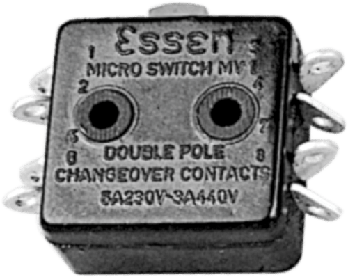
MV1( )
- Actuating force : 562 gms. (max.)
- Release force : 60 gms. (min.)
- Pretravel : 1.5 mm. (max.)
- Overtravel : Depress to case
- Movement differential : 0.8 mm. (max.)
- Free position (FP): 10.4 mm. (max.)
- Operating position (OP) : 9.32 ± 0.25 mm
- Temperature range : -65°C to +125°C
- Salient features: Plain plunger actuator Four circuit, Eight solder tags.
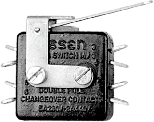
MV1( )LI
- Actuating force : 100 gms. (max.)
- Release force : 15 gms. (min.)
- Pretravel : 7.0 mm. (max.)
- Movement differential : 2.8 mm. (max.)
- Salient features: Auxiliary actuator which may be used with MV1 switch. It is a plain lever actuator of 24 mm. length. Lever ratio 5:1
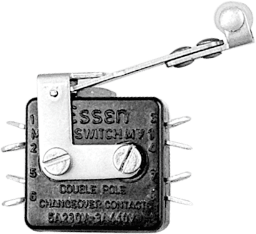
MV1( )R1
- Actuating force : 150 gms. (max.)
- Release force : 25 gms. (min.)
- Pretravel : 9.5 mm. (max.)
- Movement differential : 4.5 mm. (max.)
- Salient features: : Auxiliary actuator which may be used with MV1 switch. It is 26 mm. Long lever fitted with a free running nylon roller of 4.8 mm. diameter. Lever ratio 5.5:1
ELECTRICAL / MECHANICAL PARAMETERS
Contact resistance
Insulation resistance
Voltage proof
Terminals
Electrical life
Mechanical life
10 milliohms (max.)
1000 megaohms (min)
1 KV AC for one minute
Solder
50,000 operations
1 million operations
Electrical rating
VOLTAGE
125AC
250AC
125DC
250DC
250AC
125DC
250DC
RESISTIVE LOAD (AMPERES)
10
5
1.5(0.5)
0.5(0.25)
5
1.5(0.5)
0.5(0.25)
INDUCTIVE LOAD (AMPERES)
5
5
0.5(0.03)
0.25(0.02)
5
0.5(0.03)
0.25(0.02)
Current values have been assessed on the basis that each mechanism is used to switch only one load, either on it’s normally-open
or normally-closed contacts. When two circuits per mechanism are switched the same current values on AC may be used but on resistive and inductive DC loads the smaller values shown in brackets should be used.
Note : place ‘S’ for Silver plated and ‘G’ for Gold plated terminals in bracket ‘( )’ against ordering code of micro switches