

M SERIES
- Overview
- Characteristics
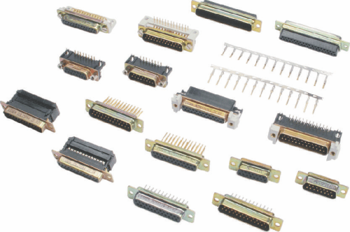
- Products
Characteristics
- Plugs (male) and sockets (female) are available in five basic shell sizes E, A,B,C and D containing 9, 15,25, 37 and 50 contacts respectively
- Contacts are available in solder bucket, PC straight/ right angle and wire wrap versions
- Solder bucket contacts accommodate wire sizes upto 0.6 sq.mm. (AWG 20) standard wire.
- Two piece insulators are made of flame retardant thermoplastic (UL94V-O).
- Trapezoidal shape of the shells ensures foolproof polarisation
- Available in rigid or float mounting versions.
- For each size of connectors, various types of hoods are available.
- Wide range of accessories can be supplied on request.
- Used in data processing, telecom , instrumentation and general electronic industries.
Technical data
Material
Shells
Insulator
Contacts
Finish
Electrical
Voltage Proof
Current rating
Voltage rating
Contact resistance
Insulation resistance
Operating temprature
Steel,zinc/ cadmium or tin plated
Flame retardant thermoplastic UL94V-O
Copper alloy
Gold over nickel (active zone)
Tin over nickel (termination zone)
or gold over nickel all over
1000V AC rms.
5A or 7.5A
300V AC rms.
10 milliohms max.
5000 Mohms min.
-55°C to +125°C
Panel Cutouts
No. of contacts
- 09
- 15
- 25
- 37
- 50
Types of mounting
Rigid
Rigid
Rigid
Rigid
Rigid
Mounting Method
Front
Rear
Front
Rear
Front
Rear
Front
Rear
Front
Rear
A±0.2
22.2
20.5
30.5
28.8
44.3
12.3
60.7
59.1
58.3
56.3
B±0.2
11.1
10.2
13.3
14.4
22.1
21.3
30.4
29.5
29.2
28.2
C±0.2
25.0
25.0
33.3
33.3
47.0
47.0
63.5
63.5
61.1
61.1
D±0.2
12.5
12.5
16.7
16.7
23.5
23.5
31.7
31.7
30.6
30.6
E±0.2
13.0
11.4
13.0
11.4
13.0
11.4
13.0
11.4
15.8
14.1
F±0.2
6.5
5.7
6.5
5.7
6.5
5.7
6.5
5.7
7.9
7.1
G±0.1
3.0
3.0
3.0
3.0
3.0
3.0
3.0
3.0
3.0
3.0
H±0.1
1.5
1.5
1.5
1.5
1.5
1.5
1.5
1.5
1.5
1.5
J±0.2
2.1
3.4
2.1
3.4
2.1
3.4
2.1
3.4
2.1
3.4
Male, Solder Bucket

Ordering Code
No. of contacts
- 09
- 15
- 25
- 37
- 50
Stamped contacts (5A)
- MO9P11 ( )
- M15 P11( )
- M 25P11( )
- M 37P11( )
- M 50P11( )
Machined contacts (7.5A)
- MDO9P 11 ( )
- MD15P 11 ( )
- MD 25 P 11 ( )
- MD 37 P 11 ( )
- MD 50P 11 ( )
Female Solder Bucket
Ordering Code
No. of contacts
- 09
- 15
- 25
- 37
- 50
Stamped contacts (5A)
- MO9S11 ( )
- M15S11 ( )
- M25S11 ( )
- M37S11 ( )
- M50S11 ( )
Machined contacts (7.5A)
- MDO9S 11 ( )
- MD15S 11 ( )
- MD25S 11 ( )
- MD37S 11 ( )
- MD50S 11 ( )
Add following at () in the ordering code above for contact finish
| Plating thickness | Gold all over | Selective gold on mating area |
|---|---|---|
Level 3 | 1 | 4 |
Level 2 | 2 | 5 |
Level 1 | 3 | 6 |
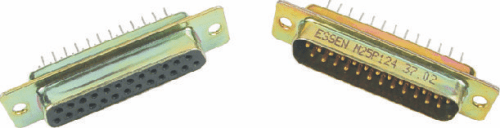
Male, PC Straight
Ordering Code
No. of contacts
- 09
- 15
- 25
- 37
- 50
Stamped contacts
(5A)
- M09P12 ( )
- M15P12 ( )
- M25P12 ( )
- M37P12 ( )
- M50P12 ( )
Machined contacts
(7.5A)
- MD09P12( )
- MD15P12( )
- MD25P12( )
- MD37P12( )
- MD50P12( )
Female, PC Straight
Ordering Code
No. of contacts
- 09
- 15
- 25
- 37
- 50
Stamped contacts
(5A)
- M09S12()
- M15S12()
- M25S12 ()
- M37S12 ()
- M50S12 ()
Machined contacts
(7.5A)
- MD09S12( )
- MD15S12 ( )
- MD 25 S12 ( )
- MD37P12( )
- MD50S12 ( )
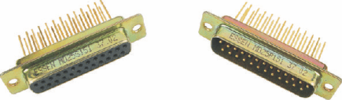
Male, Wire Wrap Machined pins (7.5A)
No. of contacts
- 09
- 15
- 25
- 37
- 50
Stamped contacts
(5A)
- MD09P15 ( )
- MD15P15 ( )
- MD25P15 ( )
- MD37P15 ( )
- MD50P15 ( )
Female, Wire Wrap Machined pins (7.5A)
No. of contacts
- 09
- 15
- 25
- 37
- 50
Stamped contacts
(5A)
- MD09S15( )
- MD15S15 ( )
- MD25S15 ( )
- MD37S15 ( )
- MD50S15( )
| No. of contacts | A | B | C | |
|---|---|---|---|---|
E | 09 | 30.6 | 25.0 | 12.5 |
A | 15 | 39.0 | 33.3 | 12.5 |
B | 25 | 52.8 | 47.0 | 12.5 |
c | 37 | 69.2 | 63.5 | 12.5 |
D | 50 | 66.6 | 61.1 | 12.5 |
Add following at () in the ordering code above for contact finish
| Plating thickness | Gold all over | Selective gold on mating area |
|---|---|---|
Level 3 | 1 | 4 |
Level 2 | 2 | 5 |
Level 1 | 3 | 6 |
7.2 mm. foot print
Row pitch 2.54 mm.
Male, PC Right Angle Machined pins (7.5A)
with guided bracket

No. of contacts
- 09
- 15
- 25
- 37
- 50
Stamped contacts
(5A)
- MD09P13 ( )
- MD15P13 ( )
- MD25P13 ( )
- MD37P13 ( )
- MD50P13 ( )
Female, PC Right Angle Machined pins (7.5A)
with guided bracket
No. of contacts
- 09
- 15
- 25
- 37
- 50
Stamped contacts
(5A)
- MD09S13( ) B
- MD15S13( ) B
- MD25S13( ) B
- MD37S13( ) B
- MD50S13( ) B
| No. of contacts | A | B | C | |
|---|---|---|---|---|
E | 09 | 25.0 | 12.5 | 30.8 |
A | 15 | 33.3 | 12.5 | 39.1 |
B | 25 | 47.0 | 12.5 | 53.0 |
c | 37 | 63.5 | 12.5 | 69.3 |
D | 50 | 61.1 | 15.4 | 66.9 |
Add following at () in the ordering code above for contact finish
| Plating thickness | Gold all over | Selective gold on mating area |
|---|---|---|
Level 3 | 1 | 4 |
Level 2 | 2 | 5 |
Level 1 | 3 | 6 |
7.2 mm. foot print
Row pitch 2.84 mm.
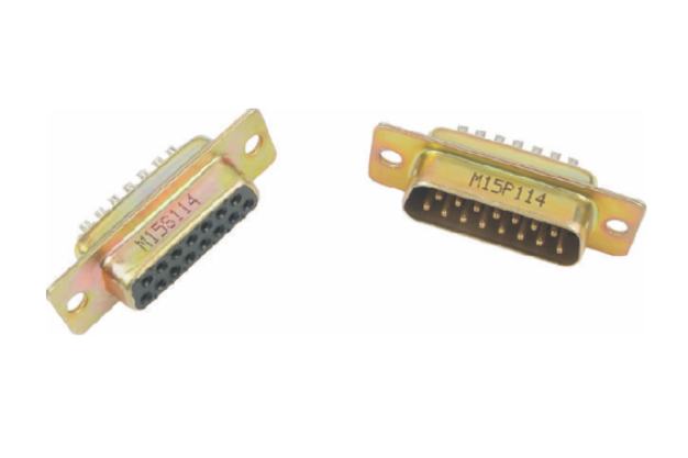
Male, PC Right Angle Machined pins (7.5A)
with guided bracket
No. of contacts
- 09
- 15
- 25
- 37
- 50
Stamped contacts
(5A)
- MD09P14 ( )B
- MD15P14 ( )B
- MD25P14 ( )B
- MD37P14 ( )B
- MD50P14 ( )B
Female, PC Right Angle Machined pins (7.5A)
with guided bracket
No. of contacts
- 09
- 15
- 25
- 37
- 50
Stamped contacts
(5A)
- MD09S14 ( )B
- MD 15S14 ( )B
- MD25S14 ( )B
- MD37S14 ( )B
- MD50S14 ( )B
| No. of contacts | A | B | C | |
|---|---|---|---|---|
E | 09 | 25.0 | 12.5 | 30.8 |
A | 15 | 33.3 | 12.5 | 39.1 |
B | 25 | 47.0 | 12.5 | 53.0 |
c | 37 | 63.5 | 12.5 | 69.3 |
D | 50 | 61.1 | 15.4 | 66.9 |
Add following at () in the ordering code above for contact finish
| Plating thickness | Gold all over | Selective gold on mating area |
|---|---|---|
Level 3 | 1 | 4 |
Level 2 | 2 | 5 |
Level 1 | 3 | 6 |
9.4 mm. foot print
Row pitch 2.54 mm.
Male, PC Right Angle Machined pins (7.5A)
with guided bracket
No. of contacts
- 09
- 15
- 25
- 37
- 50
Stamped contacts
(5A)
- MD09P16( ) B
- MD15P16 ( )B
- MD25P16 ( )B
- MD37P16 ( )B
- MD50P16 ( )B
Female, PC Right Angle Machined pins (7.5A)
with guided bracket
No. of contacts
- 09
- 15
- 25
- 37
- 50
Stamped contacts
(5A)
- MD09S16 ( )B
- MD15S16 ( )B
- MD25S16 ( )B
- MD37S16 ( )B
- MD50S16 ( )B
9.4 mm. foot print
Row pitch 2.84 mm.
| No. of contacts | A | B | C | |
|---|---|---|---|---|
E | 09 | 25.0 | 12.5 | 30.8 |
A | 15 | 33.3 | 12.5 | 39.1 |
B | 25 | 47.0 | 12.5 | 53.0 |
c | 37 | 63.5 | 12.5 | 69.3 |
D | 50 | 61.1 | 15.4 | 66.9 |
Add following at () in the ordering code above for contact finish
| Plating thickness | Gold all over | Selective gold on mating area |
|---|---|---|
Level 3 | 1 | 4 |
Level 2 | 2 | 5 |
Level 1 | 3 | 6 |
Male, PC Right Angle Machined pins (7.5A)
with guided bracket
No. of contacts
- 09
- 15
- 25
- 37
- 50
Stamped contacts
(5A)
- MD09P17 ( )B
- MD15P17 ( )B
- MD25P17 ( )B
- MD37P17 ( )B
- MD50P17 ( )B
Female, PC Right Angle Machined pins (7.5A)
with guided bracket
No. of contacts
- 09
- 15
- 25
- 37
- 50
Stamped contacts
(5A)
- MD09S17 ( )B
- MD15S17 ( )B
- MD25S17 ( )B
- MD37S17 ( )B
- MD50S17 ( )B
Add following at () in the ordering code above for contact finish
| Plating thickness | Gold all over | Selective gold on mating area |
|---|---|---|
Level 3 | 1 | 4 |
Level 2 | 2 | 5 |
Level 1 | 3 | 6 |
Ordering Code
Series
Contact type
No. of Contacts
Type of connectors
Termination Style
M
D
15
P
Stamped Contacts
(5A) - Omitted
machined contacts
(7.5) - D
09,15,25
37,50
Plug (male) - P
Socket (Female)- S
Solder Bucket -11
PC Straight -12
PC right angle
7.2 mm foot print
Row pitch 2.54mm -13**
Row pitch 2.84mm -14**
9.4 mm foot print
Row pitch 2.54mm -16**
Row pitch 2.84mm -17**
Wire wrap -15
Contact finish
Modificat-ions
1
XX
1
XX
| Plating thickness | Gold all over | Selective gold on mating area |
|---|---|---|
Level 3 | 1 | 4 |
Level 2 | 2 | 5 |
Level 1 | 3 | 6 |
**with guided bracket only.
Notes:
- Shells are mainly supplied with zinc/cadmium Tin plated shells can be supplied on request. Please add suffix ‘T’.
- D-connectors are supplied with rigid mounting.For float mounting,please add suffix ‘F’#.
- Add suffix ‘B’ for D-sub PC right angle connectors complete with guided plastic brackets duly screwed to the connector. e.g.M15P141B
- If in (3),D-sub connectors are required with bracket (guided) fitted with 4-40UNC screws,add additional suffix ‘X’, e.g.M9P141BX.
- Add suffix ‘Y’ if (3) is required with snap lock, e.g.M9P141BY or M9Pl41BXY. (With 4-40 UNC screw and snap lock).
- Add suffix ‘Z’ for D-sub PC right angle connector complete with lock block
- Add suffix ‘D’ for supply of D-sub connector with dimples on its shell (only for male connector),e.g.M25P111D or MD25P111D
Add suffix ‘V’ if in (3),D-sub connectors are required with bracket (guided) fitted with 19 mm.4-40UNC Screws e.g.M9P1418VX.