
Modern industrial machinery operates at high speed and complexity. From automated assembly lines to heavy-duty equipment, every system requires a safety mechanism that responds instantly and without fail. At the heart of this safety architecture lies the Emergency Stop Switch — a device designed not merely to stop operations, but to prevent injury, equipment damage, and hazardous outcomes with a single human action.
Emergency Stop Switches are far more than routine “off” buttons. They are a machine’s final line of defense when normal stopping functions are insufficient. For safety engineers, machine designers, and maintenance professionals, understanding how these switches are built, how they function, and which standards they must comply with is essential. A failure in any part of this system can lead to catastrophic consequences.
This guide explores the construction, purpose, and regulatory foundation behind Emergency Stop Switches, helping you design and maintain safer industrial machinery.
The Imperative Function of Emergency Stop Switches
The core principle of an Emergency Stop Switch is simple:
The emergency stop function must override all machine functions at all times.
Unlike a standard stop button, which may initiate a controlled stopping sequence, an E-stop is designed for immediate intervention during critical situations.
Distinguishing Emergency Stop from Standard Stop
- Standard stop button: Used for daily operations and controlled stopping.
- Emergency Stop Switch: A safety component meant for immediate shutdown of hazards.
According to the EN 60204 safety framework, E-stop operations fall into two categories:
- Stop Category 0: Immediate, uncontrolled stop by cutting power to actuators.
- Stop Category 1: Controlled stop using braking actions before power removal.
No matter the category, activating an Emergency Stop Switch must always lead to a safe, defined machine state.
The Fail-Safe Closed-Circuit Principle
All Emergency Stop Switches must work on a closed-circuit (fail-safe) design.
This means:
- The circuit stays energized during normal operation.
- Pressing the E-stop—or any wiring fault like a broken cable—breaks the circuit and stops the machine.
Most importantly:
Resetting the Emergency Stop Switch must never restart the machine automatically.
A separate start action must always be required.
Construction of a Modern Emergency Stop Switch
Emergency Stop Switches are engineered with strict design requirements, ensuring dependable operation even under severe conditions.
Actuator Design & Accessibility
The actuator is the operator-facing part of the switch. Standards require:
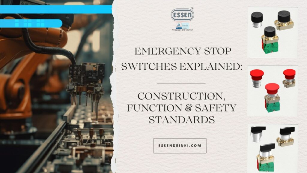
- Shape: Typically mushroom-type or palm-type for fast access (e.g., Ø 40 mm Latching Mushroom Head).
- Color:
- Actuator: RED
- Background plate: YELLOW
This RED/YELLOW combination ensures high visibility and is exclusive to emergency stops.
- Mounting cut-out: Often designed for a 5 mm panel hole.
Mechanical Latching Mechanism
A defining feature of E-stops is the press-to-lock, turn-to-release latching mechanism.
Key requirements include:
- The actuator must remain latched when pressed.
- The switch cannot generate an emergency stop signal unless it fully latches.
- The latch must resist vibration to avoid accidental release.
- The direction of resetting (turn direction) must be clearly indicated.
Contact Block & Electrical Safety
The contact block is responsible for electrical interruption. Safety requirements mandate:
- Direct (positive) opening action:
Even if contacts weld together, pressing the E-stop mechanically forces them apart. - Slow-break, self-wiping contacts:
Improves longevity and reliability. - Modular design:
Allows combinations of NO and NC contacts for complex circuits. - Shrouded terminals:
Prevent accidental contact and simplify secure wiring.
Critical Safety Standards & Compliance
Emergency Stop Switches must comply with strict international standards. Adherence ensures safety, uniformity, and regulatory acceptance.
EN ISO 13850: Design Principles
This standard governs:
- Functionality
- Visibility and color requirements
- Operator interface
- The requirement that the switch must latch and remain latched
- Mechanical and human factors for safe interaction
This ensures consistent operation across all types of machinery.
IEC 60947-5-1 & IEC 60947-5-5: Electrical Safety
- IEC 60947-5-1: Defines electrical characteristics and performance for control devices.
- IEC 60947-5-5: Focuses specifically on emergency stop devices with mechanical latching.
It mandates:
- Positive opening NC contacts
- Mechanical durability
- Latching mechanism performance
- Electrical reliability under load
Compliance with these standards, as seen in PB2-SERIES switches, ensures true industrial-grade safety.
Operational Ratings & Durability
High-quality Emergency Stop Switches must provide:
- Rated Insulation Voltage (Ui): Often 600V
- Thermal Current (Ith): Typically 10A
- Utilization categories:
- AC-15: 3A, 250V AC
- DC-13: 27A, 250V DC
- Durability:
- Mechanical: Up to 3 million operations
- Electrical: Up to 1 million operations
- Environmental Protection:
- IP65 rating for dust and water resistance
Implementation, Maintenance & Best Practices
Installing a compliant Emergency Stop Switch is only the beginning. Proper implementation and upkeep ensure long-term safety.
Strategic Placement & Accessibility
Effective placement requires:
- A full risk assessment of the machine
- Strategic positioning where hazards may occur
- Redundancy — multiple E-stops on large systems
- Unobstructed visibility and accessibility at all times
Wiring & Terminal Considerations
Safe wiring involves:
- Using appropriate conductor sizes (e.g., 2 × 1.5mm² or 1 × 2.5mm²)
- Ensuring terminals are shrouded for shock protection
- Integrating proper short-circuit protection
- Typically via 10A HRC fuses
Resetting & Operator Training
After activation:
- Manually reset the Emergency Stop Switch (twist, pull, or key).
- Use a separate start switch to restart the machine.
Operators must be trained to:
- Recognize the purpose and appearance of E-stops
- Know their location
- Follow correct activation and reset procedures
Training ensures the system works when it matters most.
Conclusion: Building Safer Industrial Systems
Emergency Stop Switches represent a sophisticated fusion of mechanical engineering, electrical safety, and regulatory compliance. Every detail—the RED/YELLOW design, mushroom actuator, closed-circuit principle, direct opening contacts, and latching mechanism—ensures the switch performs reliably during emergencies.
By choosing high-quality, compliant Emergency Stop Switches and implementing them strategically, industries protect workers, machinery, and operational continuity. Investing in reliable E-stop systems is not just regulatory compliance—it is a long-term commitment to workplace safety and operational excellence.