

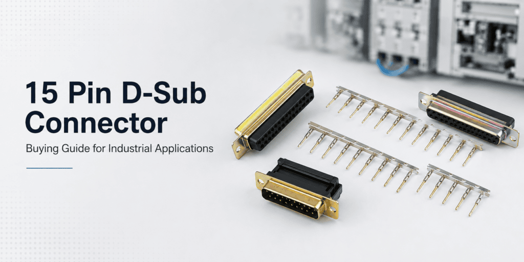
Quick answer: A 15-pin D-Sub connector (DB15) is a trapezoidal electrical connector with 15 contact pins arranged in two rows. Selecting the right one for industrial use requires evaluating pin configuration, contact material, housing, mounting style, current rating, and environmental compatibility.
Choosing the wrong connector for an industrial application can result in signal failure, equipment downtime, or costly rework. For electrical engineers, procurement teams, and OEMs across India’s growing manufacturing sector, getting the connector selection right from the start is critical.
D-Sub Connectors have been a reliable choice in industrial connectivity for decades. Among the many available configurations, the 15-pin D-Sub connector—also called the DB15 connector—is widely used across automation systems, control panels, instrumentation, and machine interfaces. Its compact 15-contact layout makes it well-suited for applications that require a moderate number of signal or power connections in a small footprint.
This guide walks you through everything you need to know before purchasing a 15-pin D-Sub connector for industrial use. From construction basics and application examples to selection criteria and common mistakes, you will find practical, technical information that supports informed procurement decisions.
What Is a 15-Pin D-Sub Connector?
A 15-pin D-Sub connector is a type of electrical connector with a distinctive trapezoidal (D-shaped) metal shell and 15 contact pins arranged in two staggered rows—one row of 8 and one row of 7. The D-shaped housing serves a functional purpose: it allows the connector to mate in only one orientation, which prevents incorrect insertion and protects the contacts.
The “DB15” designation refers to the B-size shell with 15 contacts. It is available in two standard density and high-density configurations. In industrial applications, the standard density DB15 is the most commonly used variant.
The connector consists of three main components:
- Metal shell or housing: Provides mechanical protection and EMI shielding
- Insulator body: Holds the contacts in precise alignment
- Contacts (pins or sockets): Carry electrical signals or power between mating connectors
The male connector (plug) carries pins, while the female connector (socket) carries sockets. Both halves mate together and are secured with jackscrews or locking hardware for a stable connection.
Where Are 15-Pin D-Sub Connectors Used in Industrial Applications?
The 15-pin D-Sub connector appears across a broad range of industrial environments. Its 15-contact layout supports multifunction connections where both signal and power lines need to share a single compact interface.
Common industrial application areas include:
- Industrial automation: PLCs, servo drives, and HMI panels often use DB15 connectors for I/O signal connections
- CNC machines and machine tools: Used for encoder feedback and axis control wiring
- Control panel manufacturing: Connecting field devices to control systems
- Instrumentation: Linking sensors, transmitters, and data acquisition modules
- Robotics and motion control: Multi-axis systems that require multiple signal lines in one connector
- Communication and data systems: Certain serial communication and network interface cards still use 15-pin D-Sub connectors
- Power distribution systems: Mixed layout variants can carry both signal and higher-current power contacts
Indian industrial sectors—including automotive component manufacturing, textile machinery, process control, and defense electronics—regularly specify DB15 connectors in their system designs.
Key Selection Factors for Industrial D-Sub Connectors
Selecting a 15-pin D-Sub connector requires more than matching pin count. Each factor below directly affects connector performance, reliability, and system compatibility.
Pin Configuration and Contact Arrangement
Confirm that the connector offers the correct number of contacts (15 in this case) and that the contact arrangement matches your circuit requirements. In standard density DB15 connectors, the two-row layout is fixed. However, mixed layout or high-density variants may offer different arrangements for specialized needs.
Connector Gender
Determine whether your application requires a male plug (with pins) or a female socket (with sockets). This depends on which end of the cable or panel interface you are working with. Mating pairs must always consist of one male and one female connector.
Mounting Options
Industrial D-Sub connectors are available in several mounting styles:
- Cable mount: Used for wire harnesses and field wiring
- Panel mount: Fixed to an enclosure or control panel wall
- PCB mount: Soldered directly onto a printed circuit board (right-angle or vertical)
- Rack mount: Used in 19-inch rack systems and similar enclosures
Choose the mounting method based on your installation environment and space constraints.
Housing and Shell Material
The metal shell provides both mechanical protection and EMI/RFI shielding. For industrial use, zinc-die-cast or steel shells with appropriate plating—such as zinc, cadmium, or tin—are common. Look for flame-retardant insulator materials rated UL94V-O if fire safety is a concern in your application.
Essen Deinki’sD-Sub connectors feature precision-engineered metal shells with flame-retardant thermoplastic insulators, making them suitable for demanding industrial environments.
Contact Material and Plating
Contact material determines conductivity, corrosion resistance, and overall lifespan. Copper alloy contacts are standard. Gold plating on contact surfaces improves conductivity and corrosion resistance, particularly in low-voltage signal applications. Tin plating is a more economical option suited to power contacts with higher mating cycles.
Select contact plating based on signal type, expected mating cycles, and environmental exposure.
Current and Voltage Ratings
Each contact in a DB15 connector is rated for a specific current and voltage. Standard industrial D-Sub connectors typically handle up to 5A per contact and up to 1000V dielectric strength. Exceeding these ratings can cause overheating or insulation failure.
Always verify the rated current per contact against your circuit requirements, particularly in mixed-use connectors carrying both signal and power lines.
Environmental Conditions
Industrial environments often expose connectors to moisture, oil, dust, vibration, and extreme temperatures. Consider the following:
- IP rating: Sealed or potted connectors offer protection against ingress of water and debris
- Operating temperature range: Industrial connectors typically operate from -40°C to +105°C or beyond
- Vibration and shock resistance: Applications in heavy machinery or mobile equipment need connectors with secure locking mechanisms
For environments exposed to oil, water, or contamination, select a sealed connector series. The 863 Series from Essen Deinki is designed specifically for such harsh conditions, featuring corrosion-resistant housings and sealed construction.
Cable Compatibility
Check that the connector’s wire entry design—whether solder cup, crimp, or IDC (insulation displacement)—matches the cable type and wire gauge used in your application. Crimp contacts offer consistent termination quality and ease of replacement in the field. IDC connectors, like those in the IDL Series, are suitable for ribbon cable applications.
Durability and Mating Cycles
Industrial connectors are expected to handle repeated mating and unmating. Most standard D-Sub connectors are rated for 500 to 5000 mating cycles depending on the series. Applications requiring frequent disconnection should use connectors rated for higher cycle counts.
Space and Installation Requirements
Panel cutout dimensions and connector footprint are critical in dense control panel layouts. Confirm the shell size and mounting hole spacing match your enclosure or PCB design before ordering. The C Series D-Sub connector from Essen Deinki, for example, offers an 8.1mm footprint for compact PCB installations.
How to Select the Right 15-Pin D-Sub Connector: A Step-by-Step Approach
A structured selection process reduces the risk of ordering errors and rework.
Step 1 – Define your electrical requirements: List the number of signal and power lines, current per contact, and voltage levels.
Step 2 – Identify the mounting and termination method: Determine whether you need cable mount, panel mount, or PCB mount, and confirm the termination type (crimp, solder, IDC).
Step 3 – Assess the environment: Evaluate temperature range, exposure to moisture or chemicals, and vibration levels.
Step 4 – Check mechanical constraints: Confirm the connector fits within the available panel space or PCB footprint.
Step 5 – Verify material and plating requirements: Choose housing material and contact plating based on environmental exposure and signal requirements.
Step 6 – Confirm locking and retention: Select appropriate jackscrew, clip, or latch retention based on vibration requirements.
15-Pin D-Sub Connector Buying Checklist
| Selection Criteria | What to Confirm |
| Pin count | 15 contacts (standard or high density) |
| Gender | Male (plug) or Female (socket) |
| Mounting style | Cable, panel, or PCB mount |
| Termination type | Crimp, solder cup, or IDC |
| Contact plating | Gold or tin |
| Current rating per contact | Must exceed circuit requirement |
| Voltage rating | Check dielectric strength |
| Operating temperature | Must suit environment |
| Shell material | Steel, zinc-die-cast, or other |
| IP/sealing rating | Required for harsh environments |
| Mating cycle rating | Match to application frequency |
| Footprint/panel cutout | Verify against design drawings |
Common Mistakes Industrial Buyers Should Avoid
- Selecting based on pin count alone: Two connectors with 15 pins may differ significantly in current rating, shell size, and contact plating. Always review the full specification sheet.
- Ignoring environmental ratings: A standard unsealed connector will not survive in wet or oily environments. Match the connector series to the actual operating conditions.
- Mismatching termination type with cable: A crimp connector paired with the wrong wire gauge will produce unreliable terminations. Always check the wire gauge range supported by the crimp contact.
- Overlooking mating orientation: D-Sub connectors are polarized by design, but incorrect gender selection—or ordering two male connectors—is a common procurement error. Confirm male/female requirements at both ends of the connection.
- Ignoring lifecycle and replacement: Choosing a non-standard series that is difficult to source can create maintenance challenges later. Choose connectors from established product families with long-term availability.
Why D-Sub Connectors Remain Relevant in Modern Industrial Systems
Many engineers assume that D-Sub connectors belong to an older generation of electronics. In reality, D-Sub Connectors remain widely specified across industrial automation, instrumentation, and control systems globally—including across India’s manufacturing sector. Their robust metal shell, proven shielding performance, and broad availability make them a practical, cost-effective solution for multipin industrial connections.
For new system designs and legacy machine upgrades alike, the DB15 connector continues to offer a reliable and well-understood interface.
Make the Right Decision for Your Application
Selecting the right 15-pin D-Sub connector requires careful evaluation of electrical, mechanical, and environmental requirements. Skipping any step in the selection process can lead to connector failure, unplanned downtime, or costly redesigns—outcomes that no industrial operation can afford.
Essen Deinki, a manufacturer of industrial electronic components since 1964, offers a comprehensive range of industrial D-Sub connectors including the M Series, 863 Series, IDL Series, and C Series. Each series is engineered to meet the specific demands of industrial environments, with options for sealed construction, flame-retardant materials, and a wide range of contact configurations.
If you are evaluating D-Sub Connectors for your next project—whether for a control panel, automation system, or machine interface—contact Essen Deinki’s technical team for professional guidance. Their engineers can help you identify the most suitable connector for your specific application requirements.
Frequently Asked Questions
What is the difference between a DB15 and a DE15 connector?
DB15 refers to a 15-pin D-Sub connector in the B-size shell, while DE15 uses the smaller E-size shell with a higher-density contact arrangement. Both carry 15 pins but differ in shell dimensions and contact spacing. Confirm which variant your mating connector uses before ordering.
Can a 15-pin D-Sub connector carry both signal and power in the same connector?
Yes. In mixed-layout configurations, selected contacts can carry higher current while others handle signal lines. However, always verify the current rating of each individual contact and ensure the overall connector design supports the power load required.
What termination type is best for industrial field wiring?
Crimp termination is generally preferred for industrial field wiring because it provides consistent, reliable connections and allows individual contacts to be replaced without reworking the entire connector. Solder cup types are suitable for fixed installations where rework is infrequent.
How do I know if I need a sealed or unsealed D-Sub connector for my application?
If the installation environment involves exposure to moisture, oil, coolant, dust, or other contaminants, choose a sealed connector with an appropriate IP rating. Standard unsealed D-Sub connectors are suitable for clean, enclosed environments such as control cabinets or indoor instrumentation panels.